

 0577-86833336 86807568
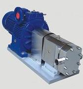
TRA Operating Principle Technical Parameter Installing Dimension Documents Downloads
1.Product Desciption:
Model TRA universal cam and rotor transfer pump (without coupling)

2.Working principle:
Operating principle
The TRA Lobe pumps basically consist of two lobe rotors which rotate synchronously inside a casing without touching each other.The two rotors divide the rotor chamber into to several smaller rooms and move in order as: a��b��c��d. At position a, only room ��if filled with medium; at position b, some medium is closed in room B; at position C, some medium is also closed in room A, and at position d, room A and B are connected with room ��; here the medium is delivered to the outlet. With this circulation, the medium (material) is delivered through the pump continuously.
3.Technical parameters:
As the rotors rotate, the spaces between the lobes and the casing are successively filled with fluid, which is transported to the discharge nozzle with a fixed amount of displacement. The pumped fluid forms a continuous stream thanks to the tolerances between the lobes and the pump casing, thus ensuring an efficient pumping.
Materials
|
Parts in contact with the product |
AISI 316L or 304 |
|
Gaskets |
EPDM |
|
Mechanical seal |
graphite/Sic/EPDM SiC/C/EPDM |
|
Internal surface finish |
Ra �� 0.4 µm |
|
External surface finish |
bright polish |
Options
Mechanical seals: SiC/SiC or TuC/SiC.
Cooled mechanical seal, pressurised double mechanical seal, lip seal or O-ring seal.
Gaskets in EPDM or PTFE.
Heating chamber (Jacket).
Isolation can.
Vertical support.
Rectangular nozzle.
Various kinds of drives and protections (gearbox drive with optional frequency converter.
pulley/mechanical drive speed selector).
Trolley and/or control panel.
Connections: clamp, SMS, RJT, etc.
Parameters
|
Serial No. |
Mode |
Volume per revolution (L) |
Suggest speed(rpm) |
Max speed (rpm) |
I,II Power(Kw) |
��Power(Kw) |
Inlet/outlet(mm) |
|
1 |
TR(A)-02 |
0.015 |
200-500 |
960 |
0.55 |
0.37 |
25 |
|
2 |
TR(A)-05 |
0.028 |
200-500 |
960 |
0.55 |
0.37 |
25 |
|
3 |
TR(A)-1 |
0.04 |
200-500 |
960 |
0.55 |
0.37 |
25 |
|
4 |
TR(A)-2 |
0.075 |
200-400 |
960 |
0.75 |
0.55 |
32 |
|
5 |
TR(A)-3 |
0.095 |
200-400 |
960 |
1.1 |
0.75 |
32 |
|
6 |
TR(A)-4 |
0.118 |
200-400 |
960 |
1.5 |
1.1 |
38 |
|
7 |
TR(A)-5 |
0.18 |
200-400 |
700 |
2.2 |
1.5 |
38 |
|
8 |
TR(A)-6 |
0.28 |
200-400 |
700 |
3 |
2.2 |
50 |
|
9 |
TR(A)-7 |
0.34 |
200-400 |
600 |
4 |
3 |
50 |
|
10 |
TR(A)-8 |
0.424 |
200-400 |
700 |
5.5 |
4 |
50 |
|
11 |
TR(A)-9 |
0.53 |
200-400 |
600 |
7.5 |
5.5 |
63.5 |
|
12 |
TR(A)-10 |
0.7 |
200-400 |
600 |
7.5 |
5.5 |
63.5 |
|
13 |
TR(A)-11 |
1.0 |
200-400 |
500 |
11 |
7.5 |
89 |
|
14 |
TR(A)-12 |
1.6 |
200-400 |
500 |
15 |
11 |
89 |
|
15 |
TR(A)-13 |
2.0 |
100-400 |
400 |
15 |
11 |
108 |
|
16 |
TR(A)-14 |
3.5 |
100-400 |
400 |
22 |
15 |
133 |
|
17 |
TR(A)-15 |
5.3 |
100-400 |
400 |
37 |
30 |
15 |
4.Installation dimensions:


Infotime:2006/6/7 Hits:21439 [Print][Close]